Driving the GDEH0154D67 e-paper display with Rust
A while ago I bought a SQFMI Watchy. It's an open source e-paper watch driven by an ESP32 that I specifically bought to hack on: the firmware is open source and you can very easily create your own watchface by cloning the firmware and directly modifying the code! And I did create my watchface, which I now recognize looks kinda bad.
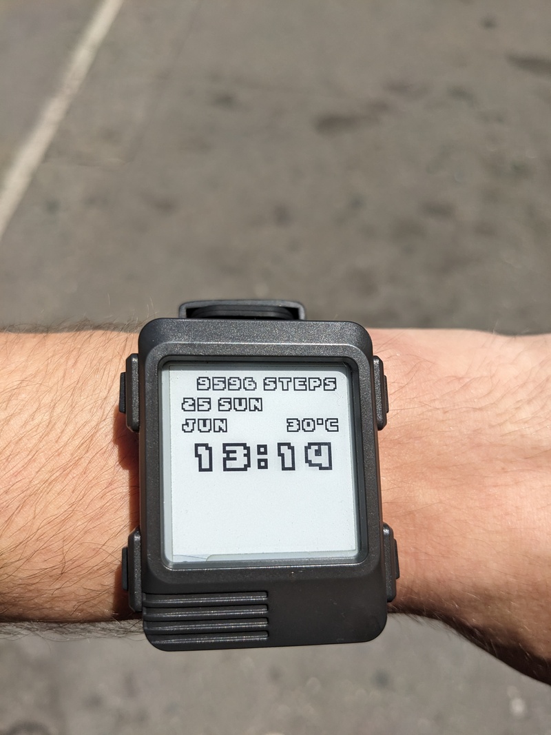
I had just bought a coffee table book on arcade videogame typefaces and I ended up picking the typeface for Passing Shot, an arcade top-down tennis game from 1988, for the watch face. It looks a lot better with color, but I had spent a lot of time encoding those glyphs into 1s and 0s and damn if I wasn't gonna use it in my crappy watch face.
I wanted to do a lot of things with this firmware: rewrite the menu, have it receive notifications from my phone via BLE, set configurable alarms... There was only one problem: the firmware is written in C++ and uses Arduino libraries. I found the documentation and quality of the code for those libraries lacking. I didn't understand how the firmware interacted with the display and the sensors. I couldn't use tagged unions. The solution? Say it with me: Rewrite👏It👏In👏Rust!
Rust on the ESP32
At the time of receiving my Watchy, Rust support for ESP32 microcontrollers was in an experimental stage and developing rapidly. At first I gave up the experiment because the HAL didn't even allow me to put the microcontroller in deep sleep, which is very important for a smartwatch!
Once that was added, I struggled with getting Espressif's forks of LLVM and rustc running on my NixOS desktop. At some point I had this very janky setup where I aliased gcc and cargo and rustc to tiny shell scripts that brought up Espressif's Docker container, running that one command and stopping right after. Eventually I managed to get this working on Nix by fetching the precompiled binaries; I still haven't figured out how to make an overlay with custom rustc and LLVM using nixpkgs.
Throughout all this the esp-rs crates kept changing the API on each release (they hadn't reached a 1.x release yet) so every time I upgraded I had to take an hour or two to fix all the compilation failures and figure out where the new APIs were and ensure that all the dependencies were on the correct version. Riveting work!
On top of all that, recently esp-hal dropped support for ESP32 chips < v3.0, and my Watchy runs on a revision 1.0 chip. I managed to get around it by setting an environment variable in my .cargo/config.toml but it doesn't exactly inspire confidence.
Despite all this I still wanted to get my Rust firmware running on the Watchy. The first step was to implement drivers for the external devices: the accelerometer, RTC, and e-paper display.
The display driver
Implementing drivers was a much smoother experience: I wanted the firmware to be async through Embassy, so all I had to do in the driver crates was to pull embedded_hal_async as a dependency and write my code against its interfaces. There are crates published on crates.io for all of the devices, but they were either incomplete or not async, so I had to write my own versions. I'll focus on the display driver here.
My revision of the Watchy (2.0) uses the GDEH0154D67 e-paper display, driven by the SSD1681 display driver. I pored over the datasheets and GxEPD2's source code and eventually ended up with a working driver for the panel.
I'd never touched a driver or a microcontroller before this so it took me many bursts of work spread over several years (with many moons passing between each burst) to figure everything out. Turns out embedded development is not so daunting as it looks! If you've worked with sockets and binary protocols before you'll find that communicating with this controller over SPI is basically the same: you write a byte corresponding to a command number, and then some data serialized according to what the datasheet tells you. The driver code itself is boring: it simply maps each SPI command described in the datasheet to a method and models data as type-safely as I could manage.
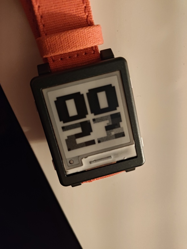
When I started testing the driver I got some very weird results! I more or less followed Watchy's code, but I wanted to experiment on the code that updates the display, because I didn't understand it and I wanted to see if I could get it to run any faster with some tweaks. A full display update would get me an empty display, and partial updates looked corrupted, save for the first one after a full update. What's going on!?
Corrupted updates
When you update the e-paper display you can choose between display mode 1 and 2:
- Mode 1 is a full display update: the whole display flashes black and white and you get a clean and artifact-free image, though it takes a few seconds to update. E-paper devices generally do a full update when you boot them up or every once in a while to clean up the image.
- Mode 2 is a "partial" update: the driver tries to only move the pixels that have changed since the last update, which is much faster than a full update. This works best when the frame hasn't changed much since the last update and usually produces artifacts that kind of look like the ink of the previous page bleeding into the next on real paper.
The SSD1681 display driver supports both monochrome black/white and 3-color black/white/red e-paper panels, like the ones you see on labels in some supermarkets. To support 3-color displays it exposes two 1-bit framebuffers: one for the black and white pixels and one for red, which I'll refer to here as b/w RAM and red RAM.
The GDEH0154D67 panel is monochrome, so it repurposes red RAM as a "previous frame" buffer for partial updates, while the b/w RAM contains the current frame. As I understand it, a partial update essentially diffs the current and previous frame buffers to produce the appropriate waveforms to transition the ink from one color to the next, so when you're driving the display you have to make sure that the previous frame buffer actually reflects the pixels that are currently on the display.
Understanding that should be enough to drive the display. My Display::draw function roughly looked like this:
- Initialize the display
- Write a frame to b/w RAM
- Update the display
- For a full update, use mode 1
- For a partial update, use mode 2
- Write the same frame to red RAM for the next partial update
This... didn't have the effect I thought it would. A full update showed a stale frame from before I had flashed the new firmare, the first partial update looked clean, but subsequent updates would corrupt the image like in the photo above. Clearly I had something wrong.
Ping-pong
While writing the driver I came across an option that the datasheet calls "ping-pong": basically when the option is on, a partial update will also swap the b/w and red RAM so that b/w ram points to the contents of red RAM and vice-versa. I thought this looked useful and wondered whether I could use it on this firmware; the datasheet mentioned that this option was disabled by default.
It took me a while to realize that this option is turned on in the OTP memory of the Watchy. It's kind of obvious in hindsight, but I had to draw a diagram and write some pseudocode to understand it correctly. Let me show you how it works in pseudo-C.
Since b/w and red RAM are not stable anymore, let's call the two RAMs RAM0 and RAM1. After a software reset (which is part of the startup sequence of the display, according to the datasheet), b/w RAM points to RAM0 and red RAM points RAM1.
typedef uint8_t ram[5000];

static ram *bw_ram;
static ram *red_ram;

void software_reset() {
    bw_ram = &RAM0;
    red_ram = &RAM1;
}
On a full update I wrote to b/w RAM, but in hindsight this didn't make much sense: partial updates are driven by the previous frame being in red RAM, so when you're doing a full update you'd have to write to both RAMs to leave the red one in place for a partial update. It makes much more sense to drive full updates exclusively from red RAM, and indeed, this turned out to fix the issue with the stale frame I was seeing earlier.
void full_update() {
    draw_on_panel(*red_ram);
}
On a partial update, as I mentioned before, b/w RAM is diffed with red RAM, which is expected to contain the previous frame. Like in subtraction, the order of the operands is important here. If ping-pong is enabled, the RAMs are also swapped.
void partial_update() {
    draw_diff_on_panel(*bw_ram, *red_ram);
    swap(&bw_ram, &red_ram);
}
Hence, the partial update sequence kind of looks like this:
uint8_t *F0 = prev_frame;
uint8_t *F1 = current_frame;

// We'll assume red RAM already contains the previous frame.
assert(memcmp(*red_ram, F0, sizeof(ram)) == 0);

write(bw_ram, F1);
partial_update();

// The pointers are now swapped, so bw_ram now points
// to the previous frame and red_ram to the current.
assert(memcmp(*bw_ram, F0, sizeof(ram)) == 0);
assert(memcmp(*red_ram, F1, sizeof(ram)) == 0);
If you're doing several partial updates in a row, ping-pong is useful because it saves you from writing to red RAM after you've written to b/w.
On a software reset though, the pointers are reset to their original values, meaning that a partial update will diff against a stale frame (unless we partially updated the display an even number of times before the reset).
software_reset();

assert(memcmp(*bw_ram, F1, sizeof(ram)) == 0);
assert(memcmp(*red_ram, F0, sizeof(ram)) == 0);
This explains the partial update corruption: after the first partial update, red RAM pointed to RAM0, and after a software reset it points back to RAM1, so I basically kept overwriting RAM0 while RAM1 was only written to during a full update.
write(bw_ram, F2);
partial_update(); // draw_diff_on_panel(F2, F0);
The fix turned out to be simple. I split the Display::draw function into two, with Display::draw_full only writing to red RAM:
- Initialize the display
- Write frame to red RAM
- Update the display using mode 1
...and Display::draw_partial writing to b/w RAM twice:
- Initialize the display
- Write the frame to b/w RAM
- Update the display using mode 2
- Write the frame to b/w RAM (which used to be red RAM, and will be red RAM after a reset)
The second write ensures that both RAMs now contain the current frame, so we always get a valid transition both with and without a software reset. This be optimized away through some internal bookkeeping, or maybe I could avoid the software reset when I know the Watchy isn't coming from an "unknown" state. Perhaps I'll explore those options in the coming days.
Future plans
Now that I finally have everything working I think I'll just implement the basics and enjoy wearing my epaper watch around, after it's been confined to a drawer for so much time. I expect you'll have some questions for me.
May I see the watchface?
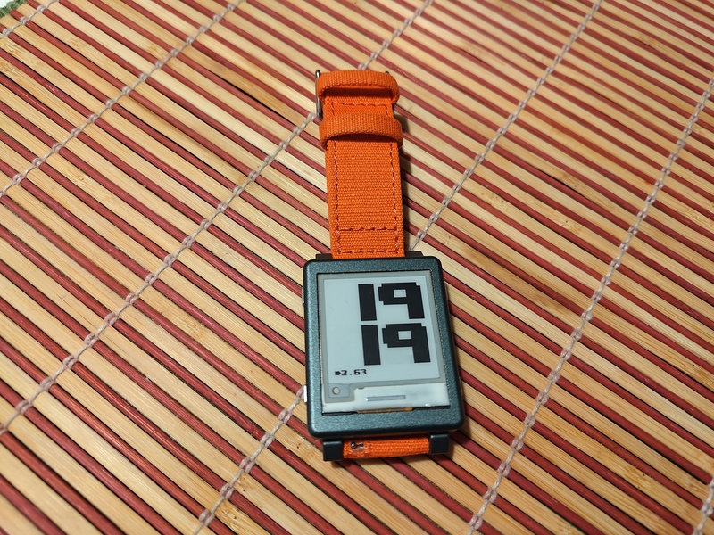
Here you go. It uses the Upheaval font, whose bytes I got from this repo, and it's running 100% pure Rust! (Except for the bootloader, I think, but I decided that it doesn't count.)
May I see the code?
It's yours, my friend, as long as you respect the terms of the license it comes with. It's still kind of messy so don't expect much outside of the drivers!
Is this AI slop?
Nope. I used it a little bit to understand some things about EPDs but I wrote all the code, and all of this post, with my own hands and using my own brain.
I'll take further questions through email or comment sections, if you find this post while browsing a site that has one of those. Thank you for reading!